|
Description:
Hydraulic steel tubes are made of material E235 (ST 37.4) or E355 (ST 52.4) according to DIN EN 10305-4 (DIN 2445/2) or DIN EN 10305-1 (DIN 2391/C). The material is +N (NBK) annealed, phosphate and oiled internally and externally. The tube ends closed with plastic plugs with continuous marking along the entire tube length. The tubes are delivered with 3.1. certification on EN 10204. |
|
Product Information of Hydraulic Steel Tubes
1. Introduction:
Chuan Kok maintains a large stock of hydraulic tubes in steel material. The hydraulic tube is a cylinder-shaped tubing device that connects to hydraulic systems, allowing fluids to flow between and inside components. They usually hold a length of about 6 meters. These steel tubes are in accordance with DIN 2391, the standard specification of steel tubes for precision application such as hydraulic and pneumatic power systems, and DIN 2445, the standard specification of seamless steel tubes for dynamic loads.
Steel tubes are available in two kinds of steel material, ST37.4 (E235N) and ST52.4 (E355N). Different materials result from differences in the working pressure that the material can withstand. Grade ST52.4 is a higher grade compared to grade ST37.4, and a higher grade of material quality can reduce wall thickness and weight while maintaining the same working pressure.
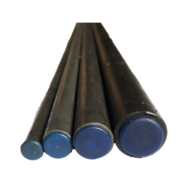
Hydraulic Steel Tubes in Difference Size
|
2. Hydraulic Steel Pipe Attributes:
Different material grades will lead to differences in attributes. For ST37.4, tensile strength ranges from 340 N/mm² to 480 N/mm², while for ST52.4, the tensile strength ranges from 490 N/mm² to 630 N/mm². Higher tensile strength means higher working pressures with reduced wall thickness, thus leading to reduced tube weight. The two different steel grades also lead to different yield strengths. The minimum yield strength for ST37.4 is 235 MPa and for ST52.4 it is 355 MPa. However, for steel tubes with an outside diameter that is less than 30MM and a thickness that is less than 3.0MM, the minimum yield strength is 10 MPa lower. There are also differences in chemical composition between ST37.4 and ST52.4. For example, the maximum carbon content for ST37.4 is 0.17%, while the maximum carbon content for ST52.4, is 0.22%. The high carbon content will make the steel harder and stronger through heat treatment. However, it will also cause the steel material to be less ductile and reduce the melting point. |
Chemical Composition (%) |
Carbon (C) |
Silicon (Si) |
Manganese (Mn) |
Phosphorus (P) |
Sulfur (S) |
E355 (ST52.4) |
⩽ 0.22 |
⩽ 0.55 |
⩽ 1.6 |
⩽ 0.045 |
⩽ 0.045 |
E235 (ST37.4) |
⩽ 0.17 |
⩽ 0.35 |
⩽ 1.2 |
⩽ 0.045 |
⩽ 0.045 |
3. Hydraulic Steel Tube Finishing:
The finishing of tubes under ST37.4 and ST52.4 are NBK, where tubes are normalized, phosphated, and oiled inside and outside. Normalizing is a type of heat treatment process. Heat treatment is done to change its mechanical properties such as hardness, yield strength, and ductility.
In the normalizing process, steel is heated to a temperature about 55˚C. This process will be continued over a period of time for a transformation namely grain refinement to occur. The steel then will be air-cooled in a room temperature. This results in the steel becoming stronger and harder. Besides, this cold drawn process brings advantages of tight dimensional tolerances, increased material strength, and improved machinability for the tube. Thus, hydraulic tubes are appropriate for use in high-performance pipe systems.
Galvanizing the tubes is also another technique. Zinc is added as an additional coating to the tubes to improve their anti-rust properties. Galvanizing can be done in a variety of ways, yet this hot-dip approach is the most popular and commonly used. The hot-dip galvanization process applies a thick layer of zinc to the melted tube before painting. Electro-galvanizing can be employed when a lighter form of zinc is needed on the tube's surface.
Hydraulic tubes can be produced in two ways: seamless or welded. As they are pulled from a billet, our hydraulic tubes are manufactured from a seamless method and do not have a weld-join or a seam.
4. The Making Of DIN EN 10305-4 Tubes:
The production process will be quite similar for both DIN EN 10305-1 and DIN EN 10305-4 tubes.
DIN EN 10305-1 and DIN EN 10305-4 tubes, also known as precision steel tubes, are cylindrical hollow sections made from cold-drawn, seamless precision steel pipes. Although both tubes may have different dimensional specifications and applications DIN EN 10305-1 (DIN 2391) and DIN EN 10305-4 (DIN 2445), both together are characterized by their high dimensional accuracy and excellent surface quality. These standards are widely used in industries whereby precision and reliability are of paramount importance.
Composition
DIN EN 10305-1 and DIN EN 10305-4 tubes are primarily made of two key materials: steel and carbon. This combination ensures the tubes are not only robust but also resistant to corrosion, making them ideal for various demanding environments.
5. The Manufacturing Process:
The production of DIN EN 10305-1 and DIN EN 10305-4 tubes involves several crucial steps to ensure their precision and quality. Here's a simplified overview:
The production of DIN EN 10305-1 and DIN EN 10305-4 tubes involves several crucial steps to ensure their precision and quality. Here's a simplified overview:
- Tube Formation
The process begins with the selection of high-quality steel, which is then cut into the desired lengths. These steel pieces are then heated and pierced to create hollow tube shells. - Cold Drawing
The raw steel is then subjected to a cold-drawing process. This involves pulling the steel through a series of dies to reduce its diameter and achieve the desired dimensions. This process not only ensures precise sizing but also enhances the mechanical properties of the tubes for tight tolerances and a smooth surface finish. - Heat Treatment
To further improve the strength and hardness of the tubes, they undergo a heat treatment process. This involves heating the tubes to a specific temperature and then cooling them rapidly. The controlled cooling process, known as quenching, imparts the desired mechanical properties to the tubes. - Surface Finish
A crucial aspect of both DIN EN 10305-1 and DIN EN 10305-4 tubes is their exceptional surface finish. This is achieved through various processes like pickling, phosphating, or passivation, depending on the application requirements in order to remove impurities and to ensure a smooth, corrosion-resistant surface.
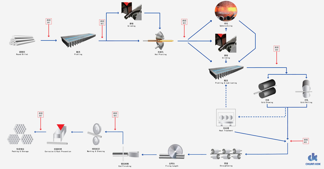
Hydraulic Steel Tubes Manufacturing Process Flow
6. Pressure Rating:
At room temperature, allowable working pressures are determined using DIN 2413. The maximum permissible running pressure and required wall thickness are determined by the yield and tensile stress values. The actual yield and tensile stress values of the tubes and pipes are validated using true copy material certifications.
At room temperature, allowable working pressures are determined using DIN 2413. The maximum permissible running pressure and required wall thickness are determined by the yield and tensile stress values. The actual yield and tensile stress values of the tubes and pipes are validated using true copy material certifications.
° C (in degree) |
° F (in degree) |
Rating Factor |
40 |
-40 |
0.90 |
120 |
248 |
1.00 |
150 |
302 |
0.89 |
175 |
347 |
0.89 |
200 |
392 |
0.83 |
250 |
482 |
NA |
To calculate the allowed working pressure at increased temperatures, multiply the allowable working pressure of the tube outer diameter and thickness by the rating factor after determining the temperature measurement.
7. Difference Between Hydraulic Tubes and Hydraulic Hoses:
Characteristics |
Hydraulic Steel Tubes |
Hydraulic Hose |
Workability and Expansion |
Ability to work and maintain shape under high heat. |
Low-level of heat resistance. When the temperature is high, they have a tendency to expand. |
Cost |
Less expensive and easily available for purchase |
Expensive |
Durability |
Highly durable |
Has a limited time for use |
8. Applications:
The versatility of DIN EN 10305-4 and DIN EN 10305-1 tubes makes them indispensable in several industries:
The versatility of DIN EN 10305-4 and DIN EN 10305-1 tubes makes them indispensable in several industries:
- Automotive Industry
These tubes are commonly used in automotive components, such as shock absorbers, steering systems, and chassis, where precision and durability are paramount. - Hydraulic Systems
DIN EN 10305-4 tubes find extensive use in hydraulic systems, ensuring efficient fluid transport and pressure control. - Mechanical Engineering
In mechanical engineering, these tubes are employed in the manufacturing of precision parts and components. - Construction
The construction industry benefits from these tubes in structural applications, ensuring stability and strength.
9. Installation:
Hydraulic tubes can be welded using standard welding processes. A bending radius of 3x the exterior tube outer diameter is suggested when cold bending tubes using an instrument tube bender or by hand. Welding Filler should be chosen in line with DIN EN 1600 and DIN EN 12072 part 1, taking into consideration the welding skill sets and application type.
There are 4 steps for hydraulics steel tubes installation:
STEP 1: Cut the tube - You can use a wheel cutter or a mechanical cutter to cut the tube
STEP 2: Bend the tube - This is usually done using a hydraulic tube bender or by hand
STEP 3: Welding - There are three steps of welding: the weld bevel process, selecting the proper welding procedures, and inspecting your work after welding.
STEP 4: Installation - After both the hydraulic component and the associated equipment have been installed, this step is completed. After you've clarified the sequence and the pipe scheme, you may use a pipe clamp to minimize tube vibration while the flow passes through.
10. Steel Composition in DIN EN 10305-4 & DIN EN 10305-1 Tubes:
The composition of steel in (DIN EN) Standard Tubes is a critical factor that defines their quality, performance, and suitability for various applications. These precision steel tubes are known for their exceptional dimensional accuracy, surface finish, and durability. To comprehend the significance of their steel composition, let's delve into the key components and their roles:
The manufacturing process, including cold drawing and heat treatment, further refines the steel composition, ensuring that the tubes meet or exceed industry standards for quality and performance. The combination of high-quality steel and precise manufacturing techniques results in tubes that are not only reliable but also capable of withstanding the rigors of various applications.
The steel composition is a well-guarded secret that underpins their exceptional quality. The careful selection of high-grade steel, controlled carbon content, and strategic use of alloying elements create tubes that are synonymous with precision, durability, and reliability. These tubes are a testament to the uncompromising standards of the precision engineering industry, where quality is paramount.
The composition of steel in (DIN EN) Standard Tubes is a critical factor that defines their quality, performance, and suitability for various applications. These precision steel tubes are known for their exceptional dimensional accuracy, surface finish, and durability. To comprehend the significance of their steel composition, let's delve into the key components and their roles:
- High-Quality Steel: Tubes are primarily constructed using high-quality steel. This choice of premium-grade steel ensures the tubes possess excellent mechanical properties, such as high tensile strength and hardness. This robust steel composition is essential for withstanding the demands of diverse applications, ranging from automotive to hydraulic systems.
- Carbon Content: Carbon content in the steel used is carefully controlled to achieve specific characteristics. The presence of carbon enhances the tubes' strength and hardness, making them resistant to wear and deformation. Carbon also contributes to the tubes' ability to maintain their structural integrity under heavy loads and harsh environmental conditions.
- Alloying Elements: In addition to steel and carbon, some tubes may incorporate alloying elements, such as manganese, silicon, and chromium. These alloying elements are added in precise proportions to further enhance the tubes' properties. For example, manganese improves ductility, while chromium contributes to corrosion resistance. The careful selection and controlled use of alloying elements ensure that these tubes meet stringent quality standards.
The manufacturing process, including cold drawing and heat treatment, further refines the steel composition, ensuring that the tubes meet or exceed industry standards for quality and performance. The combination of high-quality steel and precise manufacturing techniques results in tubes that are not only reliable but also capable of withstanding the rigors of various applications.
The steel composition is a well-guarded secret that underpins their exceptional quality. The careful selection of high-grade steel, controlled carbon content, and strategic use of alloying elements create tubes that are synonymous with precision, durability, and reliability. These tubes are a testament to the uncompromising standards of the precision engineering industry, where quality is paramount.
11. Key Differences Between DIN EN 10305-1 & DIN EN 10305-4 Tubes:
DIN EN 10305-1 and DIN EN 10305-4 are two distinct standards that govern precision steel tubes, each with its own set of specifications and applications. Here are the key differences between these two standards:
Scope and Purpose:
Tube Types:
DIN EN 10305-1 and DIN EN 10305-4 are two distinct standards that govern precision steel tubes, each with its own set of specifications and applications. Here are the key differences between these two standards:
Scope and Purpose:
- DIN EN 10305-1: Covers a wide range of precision steel tubes used in various industries, including automotive, mechanical engineering, and general engineering applications. It encompasses different tube types, sizes, and materials to serve diverse needs.
- DIN EN 10305-4: Specialized and tailored specifically to seamless cold-drawn tubes used in hydraulic and pneumatic power systems. It is designed for applications that require precision in fluid transmission and pressure control.
Tube Types:
- DIN EN 10305-1: Includes various types of precision steel tubes, such as round, square, and rectangular tubes. It offers a broad range of options to accommodate different industrial requirements.
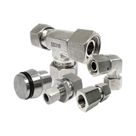
- DIN EN 10305-4: Predominantly focuses on round seamless tubes. These tubes are specifically designed for hydraulic and pneumatic systems, where precision and resistance to pressure are critical.
- DIN EN 10305-1: Manufactured using various processes, including cold drawing, cold rolling, and hot rolling. This flexibility allows for a range of production methods.
- DIN EN 10305-4: Specifies that tubes must be cold-drawn. This process ensures tight dimensional tolerances and a smooth surface finish, which are crucial for hydraulic applications.
- DIN EN 10305-1: Provides a range of dimensional tolerances, allowing for variations in size and shape depending on the specific type of precision tube.
- DIN EN 10305-4: Imposes stricter dimensional tolerances because precision is paramount in hydraulic and pneumatic systems. These tubes must meet more stringent size and shape requirements to ensure reliable performance.
- DIN EN 10305-1: Applicable in a wide array of industries, including the production of automotive components, mechanical parts, and general engineering.
- DIN EN 10305-4: Primarily used in hydraulic and pneumatic power systems, where they facilitate the reliable transmission of fluids and precise pressure control.
12. Outer Diameter and Tube Thickness Specifications:
The specifications of the tube outer diameter and tube wall thickness are according to EN 10305-4. Below Hydraulic Steel Tubes Literature will shows the preferred outside diameter, inside diameter, and wall thickness.
For more information regarding hydraulic steel tubes and their application, please refer to en.wikipedia.org/wiki/Hydraulic_machinery#Hose.2C_tubes_and_pipes
13. Hydraulic Tube (ST37.4 NBK) Working Pressure Table:
|
Description |
Working Pressure (Bar) |
Burst Pressure (Bar) |
IMPA CODE |
|
|
1 |
4MM OD x 1.0MM THK x 6 MTR |
707 |
1755 |
710701 |
|
2 |
5MM OD x 1.0MM THK x 6 MTR |
565 |
1404 |
- |
|
3 |
6MM OD x 1.0MM THK x 6 MTR |
471 |
1170 |
710702 |
|
4 |
6MM OD x 1.5MM THK x 6 MTR |
707 |
1755 |
710703 |
|
5 |
8MM OD x 1.0MM THK x 6 MTR |
353 |
878 |
710704 |
|
6 |
8MM OD x 1.5MM THK x 6 MTR |
530 |
1316 |
710705 |
|
7 |
8MM OD x 2.0MM THK x 6 MTR |
707 |
1755 |
710706 |
|
8 |
8MM OD x 2.5MM THK x 6 MTR |
883 |
2194 |
- |
|
9 |
10MM OD x 1.0MM THK x 6 MTR |
283 |
702 |
710707 |
|
10 |
10MM OD x 1.2MM THK x 6 MTR |
339 |
845 |
710708 |
|
11 |
10MM OD x 1.5MM THK x 6 MTR |
424 |
1053 |
710709 |
|
12 |
10MM OD x 2.0MM THK x 6 MTR |
565 |
1404 |
710710 |
|
13 |
10MM OD x 2.5MM THK x 6 MTR |
707 |
1755 |
- |
|
14 |
12MM OD x 1.0MM THK x 6 MTR |
236 |
585 |
710711 |
|
15 |
12MM OD x 1.2MM THK x 6 MTR |
283 |
702 |
710712 |
|
16 |
12MM OD x 1.5MM THK x 6 MTR |
353 |
878 |
710713 |
|
17 |
12MM OD x 2.0MM THK x 6 MTR |
471 |
1170 |
710714 |
|
18 |
12MM OD x 2.5MM THK x 6 MTR |
589 |
1463 |
- |
|
19 |
12MM OD x 3.0MM THK x 6 MTR |
707 |
1755 |
- |
|
20 |
14MM OD x 1.5MM THK x 6 MTR |
303 |
752 |
- |
|
21 |
14MM OD x 2.0MM THK x 6 MTR |
404 |
1003 |
- |
|
22 |
14MM OD x 2.5MM THK x 6 MTR |
505 |
1254 |
- |
|
23 |
14MM OD x 3.0MM THK x 6 MTR |
606 |
1504 |
- |
|
24 |
14MM OD x 4.0MM THK x 6 MTR |
807 |
2006 |
- |
|
25 |
15MM OD x 1.0MM THK x 6 MTR |
188 |
468 |
- |
|
26 |
15MM OD x 1.2MM THK x 6 MTR |
226 |
562 |
710715 |
|
27 |
15MM OD x 1.5MM THK x 6 MTR |
283 |
702 |
710716 |
|
28 |
15MM OD x 2.0MM THK x 6 MTR |
377 |
936 |
710717 |
|
29 |
15MM OD x 2.5MM THK x 6 MTR |
471 |
1170 |
710718 |
|
30 |
15MM OD x 3.0MM THK x 6 MTR |
565 |
1404 |
- |
|
31 |
16MM OD x 1.5MM THK x 6 MTR |
265 |
658 |
710719 |
|
32 |
16MM OD x 2.0MM THK x 6 MTR |
353 |
878 |
710720 |
|
33 |
16MM OD x 3.0MM THK x 6 MTR |
530 |
1316 |
- |
|
34 |
18MM OD x 1.5MM THK x 6 MTR |
236 |
585 |
710721 |
|
35 |
18MM OD x 2.0MM THK x 6 MTR |
314 |
780 |
710722 |
|
36 |
18MM OD x 2.5MM THK x 6 MTR |
393 |
975 |
710723 |
|
37 |
18MM OD x 3.0MM THK x 6 MTR |
471 |
1170 |
- |
|
38 |
20MM OD x 2.0MM THK x 6 MTR |
283 |
702 |
710724 |
|
39 |
20MM OD x 2.5MM THK x 6 MTR |
353 |
878 |
710725 |
|
40 |
20MM OD x 3.0MM THK x 6 MTR |
424 |
1053 |
710726 |
|
41 |
20MM OD x 3.5MM THK x 6 MTR |
495 |
1229 |
- |
|
42 |
20MM OD x 4.0MM THK x 6 MTR |
565 |
1404 |
- |
|
Description |
Working Pressure (Bar) |
Burst Pressure (Bar) |
IMPA CODE |
|
|
43 |
20MM OD x 4.5MM THK x 6 MTR |
636 |
1580 |
- |
|
44 |
20MM OD x 5.0MM THK x 6 MTR |
707 |
1755 |
- |
|
45 |
22MM OD x 2.0MM THK x 6 MTR |
257 |
638 |
710727 |
|
46 |
22MM OD x 2.5MM THK x 6 MTR |
321 |
798 |
- |
|
47 |
22MM OD x 3.0MM THK x 6 MTR |
385 |
957 |
710728 |
|
48 |
22MM OD x 4.0MM THK x 6 MTR |
514 |
1276 |
- |
|
49 |
25MM OD x 2.0MM THK x 6 MTR |
226 |
562 |
710729 |
|
50 |
25MM OD x 2.5MM THK x 6 MTR |
283 |
702 |
710730 |
|
51 |
25MM OD x 3.0MM THK x 6 MTR |
339 |
842 |
710731 |
|
52 |
25MM OD x 3.5MM THK x 6 MTR |
396 |
983 |
- |
|
53 |
25MM OD x 4.0MM THK x 6 MTR |
452 |
1123 |
- |
|
54 |
25MM OD x 5.0MM THK x 6 MTR |
565 |
1404 |
- |
|
55 |
28MM OD x 2.0MM THK x 6 MTR |
202 |
501 |
- |
|
56 |
28MM OD x 2.5MM THK x 6 MTR |
252 |
627 |
710732 |
|
57 |
28MM OD x 3.0MM THK x 6 MTR |
303 |
752 |
- |
|
58 |
28MM OD x 4.0MM THK x 3 MTR |
404 |
1003 |
- |
|
59 |
28MM OD x 5.0MM THK x 6 MTR |
505 |
1254 |
- |
|
60 |
30MM OD x 2.0MM THK x 6 MTR |
188 |
468 |
- |
|
61 |
30MM OD x 2.5MM THK x 6 MTR |
236 |
585 |
710733 |
|
62 |
30MM OD x 3.0MM THK x 6 MTR |
283 |
702 |
- |
|
63 |
30MM OD x 4.0MM THK x 6 MTR |
377 |
936 |
- |
|
64 |
30MM OD x 5.0MM THK x 6 MTR |
471 |
1170 |
- |
|
65 |
35MM OD x 2.0MM THK x 6 MTR |
161 |
401 |
- |
|
66 |
35MM OD x 2.5MM THK x 6 MTR |
202 |
501 |
710734 |
|
67 |
35MM OD x 3.0MM THK x 6 MTR |
242 |
602 |
- |
|
68 |
35MM OD x 4.0MM THK x 6 MTR |
323 |
802 |
710735 |
|
69 |
35MM OD x 5.0MM THK x 6 MTR |
404 |
1003 |
- |
|
70 |
38MM OD x 3.0MM THK x 6 MTR |
223 |
554 |
- |
|
71 |
38MM OD x 4.0MM THK x 6 MTR |
297 |
739 |
- |
|
72 |
38MM OD x 5.0MM THK x 6 MTR |
372 |
924 |
- |
|
73 |
42MM OD x 2.0MM THK x 6 MTR |
135 |
334 |
- |
|
74 |
42MM OD x 3.0MM THK x 6 MTR |
202 |
501 |
- |
|
75 |
42MM OD x 4.0MM THK x 6 MTR |
269 |
669 |
710736 |
|
76 |
42MM OD x 5.0MM THK x 6 MTR |
336 |
836 |
- |
|
77 |
50MM OD x 3.0MM THK x 6 MTR |
170 |
421 |
- |
|
78 |
50MM OD x 5.0MM THK x 6 MTR |
283 |
702 |
- |
|
79 |
60MM OD x 3.0MM THK x 6 MTR |
141 |
351 |
- |
|
80 |
60MM OD x 5.0MM THK x 6 MTR |
236 |
585 |
- |
|
81 |
65MM OD x 6.0MM THK x 6 MTR |
261 |
648 |
- |
|
82 |
75MM OD x 3.0MM THK x 6 MTR |
113 |
281 |
- |
|
83 |
1/8"NB x 2.41MM THK x 6 MTR |
649 |
1611 |
- |
|
84 |
1/4"NB x 3.02MM THK x 6 MTR |
618 |
1536 |
- |
|
Description |
Working Pressure (Bar) |
Burst Pressure (Bar) |
IMPA CODE |
|
|
85 |
3/8"NB x 3.2MM THK x 6 MTR |
523 |
1298 |
- |
|
86 |
1/2"NB x 3.0MM THK x 6 MTR |
391 |
971 |
- |
|
87 |
3/4"NB x 3.0MM THK x 6 MTR |
312 |
774 |
- |
|
88 |
1"NB x 3.5MM THK x 6 MTR |
291 |
723 |
- |
|
89 |
1"NB x 4.55MM THK x 6 MTR |
378 |
939 |
- |
|
90 |
1 1/4"NB x 4.85MM THK x 6 MTR |
321 |
797 |
- |
|
91 |
1 1/2"NB x 5.08MM THK x 6 MTR |
295 |
734 |
- |
|
92 |
2 1/2"NB x 6.3MM THK x 6 MTR |
NIL |
580 |
- |
|
93 |
1/4"OD x 1.2MM THK x 6 MTR |
534 |
1327 |
- |
|
94 |
1/4"OD x 1.5MM THK x 6 MTR |
668 |
1658 |
- |
|
95 |
3/8"OD x 1.22MM THK x 6 MTR |
362 |
899 |
- |
|
96 |
3/8"OD x 1.5MM THK x 6 MTR |
445 |
1105 |
- |
|
97 |
1/2"OD x 1.5MM THK x 6 MTR |
334 |
829 |
- |
|
98 |
3/4"OD x 2.0MM THK x 6 MTR |
297 |
737 |
- |
|
99 |
3/4"OD x 2.64MM THK x 6 MTR |
392 |
973 |
- |
|
100 |
1"OD x 3.0MM THK x 6 MTR |
334 |
829 |
- |
|
101 |
1 1/4"OD x 3.0MM THK x 6 MTR |
267 |
663 |
- |
|
102 |
1 1/4"OD x 3.25MM THK x 6 MTR |
289 |
719 |
- |
9. Hydraulic Tube (ST52.4 NBK) Working Pressure Table:
|
Description |
Working Pressure (Bar) |
Burst Pressure (Bar) |
IMPA CODE |
|
|
103 |
10MM OD x 2.0MM THK x 6 MTR |
799 |
1919 |
710710 |
|
104 |
12MM OD x 2.0MM THK x 6 MTR |
666 |
1599 |
710714 |
|
105 |
14MM OD x 1.5MM THK x 6 MTR |
428 |
1028 |
- |
|
106 |
14MM OD x 2.0MM THK x 6 MTR |
571 |
1371 |
- |
|
107 |
15MM OD x 1.5MM THK x 6 MTR |
400 |
959 |
710716 |
|
108 |
15MM OD x 2.0MM THK x 6 MTR |
533 |
1279 |
710717 |
|
109 |
15MM OD x 2.5MM THK x 6 MTR |
666 |
1599 |
710718 |
|
110 |
16MM OD x 1.5MM THK x 6 MTR |
375 |
899 |
710719 |
|
111 |
16MM OD x 2.0MM THK x 6 MTR |
500 |
1199 |
710720 |
|
112 |
16MM OD x 3.0MM THK x 6 MTR |
749 |
1799 |
- |
|
113 |
18MM OD x 1.5MM THK x 6 MTR |
333 |
800 |
710721 |
|
114 |
18MM OD x 2.0MM THK x 6 MTR |
444 |
1066 |
710722 |
|
115 |
20MM OD x 2.0MM THK x 6 MTR |
400 |
959 |
710724 |
|
116 |
20MM OD x 2.5MM THK x 6 MTR |
500 |
1199 |
710725 |
|
117 |
20MM OD x 3.0MM THK x 6 MTR |
599 |
1439 |
710726 |
|
118 |
22MM OD x 2.0MM THK x 6 MTR |
363 |
872 |
710727 |
|
119 |
25MM OD x 2.0MM THK x 6 MTR |
320 |
768 |
710729 |
|
120 |
25MM OD x 2.5MM THK x 6 MTR |
400 |
959 |
710730 |
|
121 |
25MM OD x 3.0MM THK x 6 MTR |
480 |
1151 |
710731 |
|
122 |
25MM OD x 4.0MM THK x 6 MTR |
639 |
1535 |
- |
|
123 |
25MM OD x 5.0MM THK x 6 MTR |
799 |
1919 |
- |
|
124 |
28MM OD x 2.0MM THK x 6 MTR |
285 |
685 |
- |
|
125 |
28MM OD x 3.0MM THK x 6 MTR |
428 |
1028 |
- |
|
126 |
30MM OD x 2.0MM THK x 6 MTR |
266 |
640 |
- |
|
127 |
30MM OD x 3.0MM THK x 6 MTR |
400 |
959 |
- |
|
128 |
30MM OD x 4.0MM THK x 6 MTR |
533 |
1279 |
- |
|
129 |
35MM OD x 3.0MM THK x 6 MTR |
343 |
822 |
- |
|
130 |
35MM OD x 4.0MM THK x 6 MTR |
457 |
1096 |
710735 |
|
131 |
38MM OD x 3.0MM THK x 6 MTR |
315 |
757 |
- |
|
132 |
38MM OD x 4.0MM THK x 6 MTR |
421 |
1010 |
- |
|
133 |
38MM OD x 5.0MM THK x 6 MTR |
526 |
1262 |
- |
|
134 |
42MM OD x 3.0MM THK x 6 MTR |
285 |
685 |
- |
|
135 |
42MM OD x 4.0MM THK x 6 MTR |
381 |
914 |
710736 |
|
136 |
42MM OD x 5.0MM THK x 6 MTR |
476 |
1142 |
- |
|
137 |
45MM OD x 5.0MM THK x 6 MTR |
444 |
1066 |
- |
|
138 |
50MM OD x 5.0MM THK x 6 MTR |
400 |
959 |
- |
|
139 |
50MM OD x 6.0MM THK x 6 MTR |
480 |
1151 |
- |
|
140 |
50MM OD x 10.0MM THK x 6 MTR |
799 |
1919 |
- |
|
141 |
54MM OD x 6.0MM THK x 6 MTR |
444 |
1066 |
- |
|
142 |
60MM OD x 5.0MM THK x 6 MTR |
333 |
800 |
- |
|
143 |
60MM OD x 6.0MM THK x 6 MTR |
400 |
959 |
- |
|
Description |
Working Pressure (Bar) |
Burst Pressure (Bar) |
IMPA CODE |
|
|
144 |
65MM OD x 8.0MM THK x 6 MTR |
492 |
1181 |
- |
|
145 |
66MM OD x 8.5MM THK x 6 MTR |
515 |
1236 |
- |
|
146 |
76.1MM OD x 6.3MM THK x 6 MTR |
331 |
794 |
- |
|
147 |
80MM OD x 10.0MM THK x 6 MTR |
500 |
1199 |
- |
|
148 |
90MM OD x 5.0MM THK x 6 MTR |
222 |
533 |
- |
|
149 |
90MM OD x 10.0MM THK x 6 MTR |
444 |
1066 |
- |
|
150 |
97MM OD x 12.0MM THK x 6 MTR |
494 |
1187 |
- |
|
151 |
100MM OD x 10.0MM THK x 6 MTR |
400 |
959 |
- |
|
152 |
115MM OD x 15.0MM THK x 6 MTR |
521 |
1251 |
- |
|
153 |
120MM OD x 12.0MM THK x 6 MTR |
400 |
959 |
- |
|
154 |
130MM OD x 15.0MM THK x 6 MTR |
461 |
1107 |
- |
|
155 |
150MM OD x 15.0MM THK x 6 MTR |
400 |
959 |
- |
|
156 |
190MM OD x 20.0MM THK x 6 MTR |
421 |
1010 |
- |
|
157 |
2"OD x 5.9MM THK x 6 MTR |
464 |
1114 |
- |
|
158 |
2"OD x 6.0MM THK x 6 MTR |
472 |
1133 |
- |
|
|
FAQ Of Hydraulic Steel Tubes
What are the diameter sizes available? What is the standard length for hydrailics steel
tubes?
tubes?
The sizes of hydraulics steel tubes range from 4mm to 130mm outer diameter. They typically have a length of 6 meter long.
What are the functions of hydraulics steel tubes?
The function of hydraulic steel tube is to convey liquid fluids to among hydraulics components, fittings, valves, flanges, and other tools. They are suitable in high performance piping system application.
What are the chemical composition for hydraulics steel tubes?
Hydraulics steel tubes consist of Carbon (C), Silicon (Si), Manganese (Mn), Phosphorus (P), Sulfur (S).
What are the material specifications of hydraulics steel tubes?
There are two types of material grade which are ST52.4 and ST37.4. Compared to ST37.4, ST52.4 has higher tensile strength and
higher permissible working pressures by reduced tube wall thickness. It leads to reduced system overall weight.
higher permissible working pressures by reduced tube wall thickness. It leads to reduced system overall weight.
What is the finishing used by hydraulics tubes?
The hydraulics steel tubes surface finishing is NBK where the tubes are phosphate and normalized which is corrosion resistance.
Is hydraulics steel tubes suitable for welding?
Yes. Tubes of ST37.4 and ST52.4 are suitable for welding according to usual techniques.
Clients who viewed this product also: